990 Smt 2013
![]()
OWNER'S MANUAL 2013
990 Supermoto T EU
990 Supermoto T AUS/UK
990 Supermoto T FR
Art. no. 3211957en

Congratulations on your decision to purchase a KTM motorcycle. You are now the owner of a state-of-the-art sports motorcycle that will give you enormous pleasure if you service and maintain it accordingly.
We wish you a lot of enjoyment in riding this vehicle.
Please enter the serial numbers of your vehicle below.
| Chassis number/type label | Dealer's stamp |
| Engine number ( p. 21) | |
| Key number ( p. 21) | |
The owner's manual contained the latest information for this model at the time of going to print. Minor differences due to developments in design cannot be ruled out completely.
All specifications are non-binding. KTM Sportmotorcycle AG specifically reserves the right to modify or delete technical specifications, prices, colors, forms, materials, services, designs, equipment, etc., without prior notice and without specifying reasons, to adapt these to local conditions, as well as to stop production of a particular model without prior notice. KTM accepts no liability for delivery options, deviations from illustrations and descriptions, as well as printing and other errors. The models portrayed partly contain special equipment that does not belong to the regular scope of delivery.
© 2012 KTM-Sportmotorcycle AG, Mattighofen Austria All rights reserved
Reproduction, even in part, as well as copying of all kinds, is permitted only with the express written permission of the copyright owner.

ISO 9001(12 100 6061)
According to the international quality management standard ISO 9001, KTM uses quality assurance processes that lead to the maximum possible quality of the products.
Issued by: TÜV Management Service
KTM-Sportmotorcycle AG
5230 Mattighofen, Austria
TABLE OF CONTENTS
| 1 | MEANS OF REPRESENTATION ........................................ | 7 | |
| 1.1 | Symbols used ...................................................... | 7 | |
| 1.2 | Formats used....................................................... | 7 | |
| 2 | SAFETY ADVICE.............................................................. | 8 | |
| 2.1 | Use definition - intended use ................................ | 8 | |
| 2.2 | Safety advice....................................................... | 8 | |
| 2.3 | Degrees of risk and symbols .................................. | 9 | |
| 2.4 | Tampering warning............................................... | 9 | |
| 2.5 | Safe operation ................................................... | 10 | |
| 2.6 | Protective clothing ............................................. | 11 | |
| 2.7 | Work rules......................................................... | 11 | |
| 2.8 | Environment...................................................... | 11 | |
| 2.9 | Owner's Manual ................................................. | 12 | |
| 3 | IMPORTANT NOTES...................................................... | 13 | |
| 3.1 | Guarantee, warranty ........................................... | 13 | |
| 3.2 | Operating substances ......................................... | 13 | |
| 3.3 | Spare parts, accessories ..................................... | 13 | |
| 3.4 | Service ............................................................. | 13 | |
| 3.5 | Figures ............................................................. | 14 | |
| 3.6 | Customer service................................................ | 14 | |
| 4 | VIEW OF VEHICLE ........................................................ | 16 | |
| 4.1 | View of vehicle, front left side (example) .............. | 16 | |
| 4.2 | View of vehicle, rear right side (example).............. | 18 | |
| 5 | SERIAL NUMBERS ....................................................... | 20 | |
| 5.1 | Chassis number ................................................. | 20 | |
| 5.2 | Type label ......................................................... | 20 | |
| 5.3 | Key number....................................................... | 21 | |
| 5.4 | Engine number .................................................. | 21 | |
| 5.5 | Fork part number ............................................... | 22 | |
| 3 | |||
| 5.6 | Shock absorber part number ............................... | 22 | |
| 6 CONTROLS................................................................... | 23 | ||
| 6.1 | Clutch lever....................................................... | 23 | |
| 6.2 | Hand brake lever................................................ | 23 | |
| 6.3 | Throttle grip ...................................................... | 24 | |
| 6.4 | Horn button....................................................... | 24 | |
| 6.5 | Light switch ...................................................... | 25 | |
| 6.6 | Headlight flasher switch ..................................... | 25 | |
| 6.7 | Turn signal switch.............................................. | 26 | |
| 6.8 | Emergency OFF switch ....................................... | 26 | |
| 6.9 | Electric starter button......................................... | 27 | |
| 6.10 | Ignition/steering lock.......................................... | 27 | |
| 6.11 | Immobilizer ....................................................... | 28 | |
| 6.12 | Combination instrument ..................................... | 28 | |
| 6.12.1 | Overview ....................................................... | 28 | |
| 6.12.2 | Function buttons ........................................... | 29 | |
| 6.12.3 | Tachometer ................................................... | 29 | |
| 6.12.4 | indicator lamps.............................................. | 30 | |
| 6.12.5 | Display ......................................................... | 31 | |
| 6.12.6 | Speed display................................................ | 32 | |
| 6.12.7 | Setting kilometers or miles ............................. | 32 | |
| 6.12.8 | Time............................................................. | 33 | |
| 6.12.9 | Setting the clock ........................................... | 33 | |
| 6.12.10 | ODO display .................................................. | 34 | |
| 6.12.11 | Setting/resetting display TRIP 1 ...................... | 34 | |
| 6.12.12 | Setting/resetting display TRIP 2 ...................... | 35 | |
| 6.12.13 | TRIP F display............................................... | 36 | |
| 6.12.14 | Ambient temperature indicator........................ | 36 | |
| 6.12.15 | Setting the temperature units.......................... | 36 | |
TABLE OF CONTENTS
| 6.12.16 | Warning of icy roads....................................... | 37 |
| 6.12.17 | Coolant temperature indicator ......................... | 38 |
6.13 Hazard warning flasher switch/hazard warning
| flasher .............................................................. | 38 | ||
| 6.14 | Socket for electrical accessories .......................... | 39 | |
| 6.15 | Opening the filler cap......................................... | 39 | |
| 6.16 | Closing the filler cap .......................................... | 40 | |
| 6.17 | Seat lock........................................................... | 41 | |
| 6.18 | Tool set............................................................. | 41 | |
| 6.19 | Handrails .......................................................... | 42 | |
| 6.20 | Helmet lock....................................................... | 42 | |
| 6.21 | Luggage rack plate............................................. | 43 | |
| 6.22 | Passenger footrests ............................................ | 43 | |
| 6.23 | Shift lever ......................................................... | 44 | |
| 6.24 | Foot brake lever ................................................. | 45 | |
| 6.25 | Side stand......................................................... | 45 | |
| 7 | PREPARING FOR USE................................................... | 46 | |
| 7.1 | Information on first use ...................................... | 46 | |
| 7.2 | Running in the engine ........................................ | 47 | |
| 7.3 | Loading the vehicle ............................................ | 47 | |
| 8 | RIDING INSTRUCTIONS................................................ | 50 | |
8.1 Checks and maintenance measures when
| preparing for use................................................ | 50 | |
| 8.2 | Starting............................................................. | 51 |
| 8.3 | Starting off........................................................ | 53 |
| 8.4 | Shifting, riding .................................................. | 53 |
| 8.5 | Braking ............................................................. | 56 |
| 8.6 | Stopping, parking............................................... | 58 |
| 8.7 | Transport .......................................................... | 59 |
| 4 | |||
| 8.8 | Refueling .......................................................... | 60 | |
| 9 | SERVICE SCHEDULE .................................................... | 62 | |
| 9.1 | Service schedule................................................ | 62 | |
| 10 | TUNING THE CHASSIS ................................................. | 65 | |
| 10.1 | Fork/shock absorber ........................................... | 65 | |
| 10.2 | Adjusting the compression damping of the fork..... | 65 | |
| 10.3 | Adjusting the rebound damping of the fork ........... | 66 | |
| 10.4 | Adjusting the spring preload of the fork................ | 67 | |
| 10.5 | Compression damping of the shock absorber......... | 69 | |
10.6 Adjusting the low-speed compression damping of
| the shock absorber............................................. | 69 |
10.7 Adjusting the high-speed compression damping
| of the shock absorber ......................................... | 70 |
10.8 Adjusting the rebound damping of the shock
| absorber............................................................ | 71 |
10.9 Adjusting the spring preload of the shock
| absorber............................................................ | 72 |
| 11 SERVICE WORK ON THE CHASSIS................................. | 75 |
11.1 Raising the motorcycle with the rear wheel
| stand ................................................................ | 75 |
11.2 Taking the motorcycle off of the rear wheel
| stand ................................................................ | 75 |
11.3 Raising the motorcycle with the front wheel
| stand ................................................................ | 76 |
11.4 Taking the motorcycle off of the front wheel
| stand ................................................................ | 76 | |
| 11.5 | Bleeding the fork legs......................................... | 77 |
| 11.6 | Removing the seat ............................................. | 77 |
| 11.7 | Mounting the seat .............................................. | 78 |
| 11.8 | Reinstalling the fuel tank.................................... | 78 |
| TABLE OF CONTENTS | ||
| 11.9 | Positioning the fuel tank..................................... | 79 |
| 11.10 | Mounting the helmet lock on the vehicle .............. | 80 |
| 11.11 | Removing the mask spoiler ................................. | 81 |
| 11.12 | Installing the mask spoiler .................................. | 83 |
| 11.13 | Checking the chain for dirt.................................. | 84 |
| 11.14 | Cleaning the chain ............................................. | 84 |
| 11.15 | Checking the chain tension ................................. | 86 |
| 11.16 | Adjusting the chain tension................................. | 87 |
| 11.17 | Checking the chain, rear sprocket, engine | |
| sprocket and chain guide.................................... | 89 | |
| 11.18 | Adjusting the basic position of the clutch lever ..... | 92 |
| 11.19 | Checking/rectifying the fluid level of the | |
| hydraulic clutch................................................. | 92 | |
| 12 BRAKES....................................................................... | 94 | |
| 12.1 | ABS/antilock brake system.................................. | 94 |
12.2 Adjusting the basic position of the hand brake
| lever ................................................................. | 95 | |
| 12.3 | Checking the front brake discs ............................ | 95 |
| 12.4 | Checking the front brake fluid level ..................... | 96 |
| 12.5 | Adding front brake fluid x................................. | 97 |
| 12.6 | Checking the front brake linings .......................... | 98 |
| 12.7 | Checking the free travel of the foot brake lever...... | 99 |
12.8 Adjusting the basic position of the foot brake
| lever ............................................................... | 100 | |
| 12.9 | Checking the rear brake disc ............................. | 101 |
| 12.10 | Checking the rear brake fluid level..................... | 101 |
| 12.11 | Adding rear brake fluid x................................ | 102 |
| 12.12 | Checking the rear brake linings ......................... | 104 |
| 5 | |||
| 13 | WHEELS, TIRES ......................................................... | 106 | |
| 13.1 | Removing the front wheel x............................ | 106 | |
| 13.2 | Installing the front wheel x............................. | 107 | |
| 13.3 | Removing the rear wheel x.............................. | 109 | |
| 13.4 | Installing the rear wheel x.............................. | 111 | |
| 13.5 | Checking the rear hub rubber dampers x.......... | 113 | |
| 13.6 | Checking the tire condition ............................... | 114 | |
| 13.7 | Checking the tire air pressure............................ | 115 | |
| 14 | ELECTRICAL SYSTEM ................................................. | 117 | |
| 14.1 | Removing the battery x.................................. | 117 | |
| 14.2 | Installing the battery x................................... | 119 | |
| 14.3 | Recharging the battery x................................ | 120 | |
| 14.4 | Changing the main fuse.................................... | 122 | |
| 14.5 | Changing the ABS fuses ................................... | 124 | |
14.6 Changing the fuses of individual power
| consumers....................................................... | 125 | |
| 14.7 | Changing the headlight bulb ............................. | 127 |
| 14.8 | Changing the parking light bulb......................... | 129 |
| 14.9 | Changing the turn signal bulb ........................... | 131 |
| 14.10 | Changing the brake light bulb ........................... | 131 |
| 14.11 | Changing the tail light bulbs ............................. | 136 |
| 14.12 | Changing the license plate lamp........................ | 141 |
| 14.13 | Checking the headlight setting .......................... | 143 |
| 14.14 | Adjusting the headlight range............................ | 143 |
| 14.15 | Activating/deactivating the ignition key .............. | 144 |
| 15 COOLING SYSTEM ...................................................... | 149 | |
| 15.1 | Cooling system ................................................ | 149 |
| 15.2 | Checking the antifreeze and coolant level ........... | 149 |
| TABLE OF CONTENTS | 6 | ||||||
| 15.3 | Checking the coolant level in the compensating | 23 | TECHNICAL DATA....................................................... | 188 | |||
| tank................................................................ | 152 | 23.1 | Engine ............................................................ | 188 | |||
| 15.4 | Draining the coolant x.................................... | 153 | 23.2 | Engine tightening torques ................................. | 189 | ||
| 15.5 | Filling/bleeding the cooling system x............... | 154 | 23.3 | Capacities ....................................................... | 192 | ||
| 16 | TUNING THE ENGINE................................................. | 157 | 23.3.1 | Engine oil ................................................... | 192 | ||
| 16.1 | Checking the play in the throttle cable ............... | 157 | 23.3.2 | Coolant ....................................................... | 192 | ||
| 16.2 | Adjusting the play in the throttle cable x.......... | 158 | 23.3.3 | Fuel ........................................................... | 193 | ||
| 16.3 | Plug-in connection, ignition timing map ............. | 158 | 23.4 | Chassis ........................................................... | 193 | ||
| 16.4 | Adjusting the ignition curve to the fuel quality .... | 159 | 23.5 | Electrical system.............................................. | 194 | ||
| 16.5 | Checking the basic position of the shift lever ...... | 160 | 23.6 | Tires ............................................................... | 195 | ||
| 16.6 | Adjusting the basic position of the shift | 23.7 | Fork................................................................ | 195 | |||
| lever x.......................................................... | 160 | 23.8 | Shock absorber................................................ | 196 | |||
| 17 SERVICE WORK ON THE ENGINE ................................ | 162 | 23.9 | Chassis tightening torques ................................ | 198 | |||
| 17.1 | Checking the engine oil level............................. | 162 | 24 | SUBSTANCES ............................................................ | 202 | ||
| 17.2 | Changing the engine oil and filter, cleaning the | 25 | AUXILIARY SUBSTANCES ........................................... | 206 | |||
| oil screens x.................................................. | 163 | 26 | STANDARDS .............................................................. | 209 | |||
| 17.3 | Draining the engine oil and filter, cleaning the | 163 | INDEX ............................................................................... | 210 | |||
| oil screens x.................................................. | |||||||
| 17.4 | Filling up with engine oil x............................. | 168 | |||||
| 17.5 | Adding engine oil............................................. | 169 | |||||
| 18 | CLEANING, CARE ....................................................... | 170 | |||||
| 18.1 | Cleaning motorcycle ......................................... | 170 | |||||
18.2 Checks and maintenance measures for winter
| operation......................................................... | 172 | ||
| 19 | STORAGE................................................................... | 174 | |
| 19.1 | Storage ........................................................... | 174 | |
| 19.2 | Preparing for use after storage........................... | 176 | |
| 20 | TROUBLESHOOTING .................................................. | 177 | |
| 21 | IMMOBILIZER BLINK CODE ........................................ | 180 | |
| 22 | ENGINE CONTROL BLINK CODE.................................. | 182 | |
| 1 | MEANS OF REPRESENTATION | 7 |
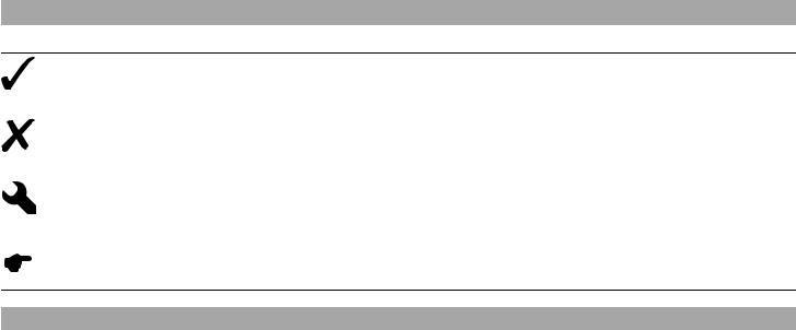
1.1 Symbols used
The meaning of specific symbols is described below.
Indicates an expected reaction (e.g. of a work step or a function).
Indicates an unexpected reaction (e.g. of a work step or a function).
All work marked with this symbol requires specialist knowledge and technical understanding. In the interest of your own safety, have these jobs performed by an authorized KTM workshop. There, your motorcycle will be optimally cared for by specially trained experts using the specialist tools required.
Indicates a page reference (more information is provided on the specified page).
1.2 Formats used
The typographical formats used in this document are explained below.
| Specific name | Identifies a proprietary name. |
| Name® | Identifies a protected name. |
| Brand™ | Identifies a brand available on the open market. |

2.1 Use definition - intended use
KTM sport motorcycles are designed and constructed to meet the normal demands of regular road operation but not for use on race courses or offroad.
Info
The motorcycle is only authorized for operation on public roads in the homologated version.
2.2 Safety advice
A number of safety instructions need to be followed to operate the vehicle safely. Therefore, read this manual carefully. The safety instructions are highlighted in the text and are referred to at the relevant passages.
Info
The vehicle has various information and warning labels at prominent locations. Do not remove information/warning labels. If they are missing, you or others may not recognize dangers and may therefore be injured.
![]()
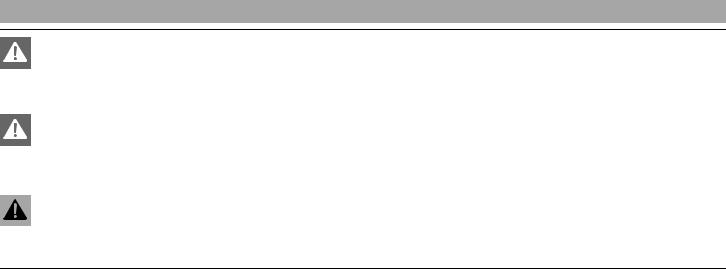
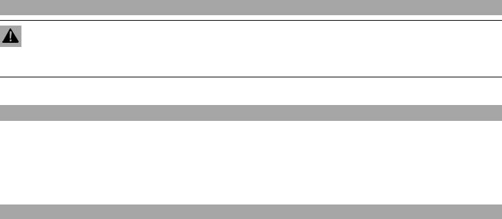
2.3 Degrees of risk and symbols
Danger
Identifies a danger that will immediately and invariably lead to fatal or serious permanent injury if the appropriate measures are not taken.
Warning
Identifies a danger that is likely to lead to fatal or serious injury if the appropriate measures are not taken.
Caution
Identifies a danger that may lead to minor injuries if the appropriate measures are not taken.
Note
Identifies a danger that will lead to considerable machine and material damage if the appropriate measures are not taken.
Warning
Identifies a danger that will lead to environmental damage if the appropriate measures are not taken.
2.4 Tampering warning
Tampering with the noise control system is prohibited. Federal law prohibits the following acts or the causing thereof:
1 The removal or rendering inoperative by any person other than for purposes of maintenance, repair, or replacement, of any device or element of design incorporated into any new vehicle for the purpose of noise control prior to its sale or delivery to the ultimate purchaser or while it is in use, or
2 the use of the vehicle after such device or element of design has been removed or rendered inoperative by any person.
Among those acts presumed to constitute tampering are the acts listed below:
1 Removal or puncturing of the main silencer, baffles, header pipes or any other components which conduct exhaust gases.
2 Removal or puncturing of any part of the intake system.
3 Lack of proper maintenance.
4 Replacing any moving part of the vehicle, or parts of the exhaust or intake system, with parts other than those specified by the manufacturer.
2.5 Safe operation
Danger
Danger of accidents Danger arising from the rider's judgement being impaired.
– Do not operate the vehicle while under the influence of alcohol, drugs and certain medications or physically or mentally impaired.
Danger
Danger of poisoning Exhaust gases are toxic and inhaling them may result in unconsciousness and/or death.
– When running the engine, always make sure there is sufficient ventilation, and do not start or run the engine in an enclosed space without an effective exhaust extraction system.
Warning
Danger of burns Some vehicle components become very hot when the vehicle is operated.
– Do not touch hot components such as exhaust system, radiator, engine, shock absorber, and the brake system. Allow these components to cool down before starting work on them.
Only operate the vehicle when it is in perfect technical condition, in accordance with its intended use, and in a safe and environmentally compatible manner.
The vehicle should only be used by trained persons. An appropriate driver's license is needed to ride the vehicle on public roads. Have malfunctions that impair safety promptly eliminated by an authorized KTM workshop.
Adhere to the information and warning labels on the vehicle.
2.6 Protective clothing
Warning
Risk of injury Missing or poor protective clothing presents an increased safety risk.
– Wear protective clothing (helmet, boots, gloves, pants and jacket with protectors) every time you ride the vehicle. Always wear protective clothing that is in good condition and meets the legal requirements.
In the interest of your own safety, KTM recommends that you only operate the vehicle while wearing protective clothing.
2.7 Work rules
Special tools are necessary for certain tasks. The tools are not contained in the vehicle but can be ordered under the number in parentheses. E.g.: bearing puller (15112017000)
During assembly, non-reusable parts (e.g. self-locking screws and nuts, seals and seal rings, O-rings, pins, lock washers) must be replaced by new parts.
In some instances, a thread locker (e.g. Loctite ®) is required. The manufacturer instructions for use must be followed.
After disassembly, clean the parts that are to be reused and check them for damage and wear. Change damaged or worn parts. After you complete the repair or service work, check the operating safety of the vehicle.
2.8 Environment
If you use your motorcycle responsibly, you can ensure that problems and conflicts do not occur. To protect the future of the motorcycle sport, make sure that you use your motorcycle legally, display environmental consciousness, and respect the rights of others.
When disposing of used oil, other operating and auxiliary fluids, and used components, comply with the laws and regulations of the respective country.
Because motorcycles are not subject to the EU regulations governing the disposal of used vehicles, there are no legal regulations that pertain to the disposal of an end-of-life motorcycle. Your authorized KTM dealer will be glad to advise you.

2.9 Owner's Manual
It is important that you read this Owner's Manual carefully and completely before making your first trip. The Owner's Manual contains useful information and many tips on how to operate, handle, and maintain your motorcycle. Only then will you find out how to customize the vehicle ideally for your own use and how you can protect yourself from injury.
Keep the Owner's Manual in an accessible place to enable you to refer to it as needed.
If you would like to know more about the vehicle or have questions on the material you read, please contact an authorized KTM dealer. The Owner's Manual is an important component of the vehicle and should be handed over to the new owner if the vehicle is sold.

3.1 Guarantee, warranty
The work prescribed in the service schedule must be carried out by an authorized KTM workshop only and confirmed in the customer's service record and in the KTM dealer.net; otherwise, all warranty claims will be void. No warranty claims can be considered for damage resulting from manipulations and/or alterations to the vehicle.
Additional information on the guarantee or warranty and the procedures involved can be found in the service record.
3.2 Operating substances
The fuels and lubricants named in the owner's manual must be used according to specifications.
3.3 Spare parts, accessories
For your own safety, only use spare parts and accessory products that are approved and/or recommended by KTM and have them installed by an authorized KTM workshop. KTM accepts no liability for other products and any resulting damage or loss.
Certain spare parts and accessory products are specified in parentheses in the descriptions. Your KTM dealer will be glad to advise you.
The current KTM PowerParts for your vehicle can be found on the KTM website.
International KTM Website: http://www.ktm.com
3.4 Service
A prerequisite for perfect operation and prevention of premature wear is that the service, care, and tuning work on the engine and chassis is properly carried out as described in the Owner's Manual. Incorrect adjustment and tuning of the engine and chassis can lead to damage and breakage of components.
Use of the vehicle under difficult conditions, such in rain, high heat or with a heavy load, can lead to considerably more rapid wear of components such as the drive train, brake system, or suspension components. For this reason, it may be necessary to inspect or replace parts before the next scheduled service.
It is imperative that you adhere to the stipulated run-in times and service intervals. If you observe these exactly, you will ensure a much longer service life for your motorcycle.

3.5 Figures
The figures contained in the manual may depict special equipment.
In the interest of clarity, some components may be shown disassembled or may not be shown at all. It is not always necessary to disassemble the component to perform the activity in question. Please follow the instructions in the text.
3.6 Customer service
Your authorized KTM dealer will be happy to answer any questions you may have on your vehicle and KTM.
A list of authorized KTM dealers can be found on the KTM website.
International KTM Website: http://www.ktm.com
15
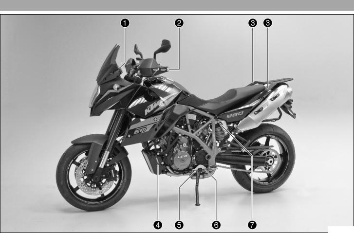
4.1 View of vehicle, front left side (example)
L00600-10

| 4 | VIEW OF VEHICLE | 17 |
| 1 | Function buttons ( p. 29) |
1 indicator lamps ( p. 30)
2 Clutch lever ( p. 23)
3 Handrails ( p. 42)
4 Level viewer, engine oil
5 Shift lever ( p. 44)
6 Engine number ( p. 21)
7 Compression damping of the shock absorber ( p. 69)

4.2 View of vehicle, rear right side (example)
L00601-10
![]()
1 Seat lock ( p. 41)
2 Light switch ( p. 25)
| 2 | Headlight flasher switch ( p. 25) |
| 2 | Turn signal switch ( p. 26) |
2 Horn button ( p. 24)
3 Filler cap
4 Emergency OFF switch ( p. 26)
4 Electric starter button ( p. 27)
5 Hand brake lever ( p. 23)
6 Fork rebound setting and spring preload setting
7 Passenger footrests ( p. 43)
8 Shock absorber setting, spring preload adjuster
9 Foot brake lever ( p. 45)
10 Chassis number/type label
11 Fork compression adjustment
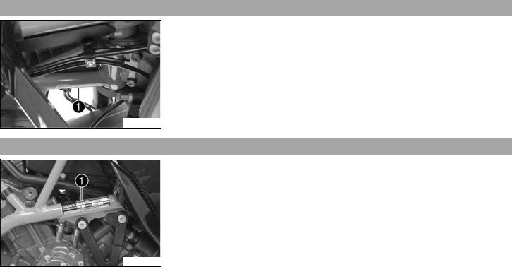
5.1 Chassis number
Chassis number 1 is embossed in the steering head at the right.
L00604-10
5.2 Type label
Type label 1 is located on the upper frame tube on the right.
L00603-10
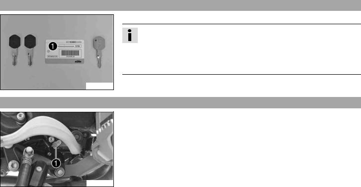
5.3 Key number
The Code number 1 key number can be found on the KEYCODECARD.
Info
You need the key number to order a spare key. Keep the KEYCODECARD in a safe place.
Use the orange programming key to activate and deactivate the black ignition key. Keep the orange programming key in a safe place: it must only be used for learning and programming functions.
700563-01
5.4 Engine number
The engine number 1 is stamped on the left side of the engine under the engine sprocket.
L00602-10
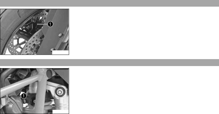
5.5 Fork part number
The fork part number 1 is stamped on the inner side of the fork stub.
B00606-10
5.6 Shock absorber part number
The shock absorber part number 1 is stamped on the top of the shock absorber above the adjusting ring on the engine side.
L00606-10
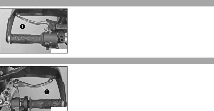
6.1 Clutch lever
The clutch lever 1 is fitted on the left side of the handlebar.
The clutch is hydraulically operated and self-adjusting.
B00608-10
6.2 Hand brake lever
The hand brake lever 1 is fitted on the right side of the handlebar.
The front brake is engaged using the hand brake lever.
B00609-10

6.3 Throttle grip
The throttle grip 1 is fitted on the right side of the handlebar.
B00655-10
6.4 Horn button
The horn button 1 is fitted on the left side of the handlebar.
Possible states
• Horn button  in basic position
• Horn button  pressed – The horn is operated in this position.
B00656-12
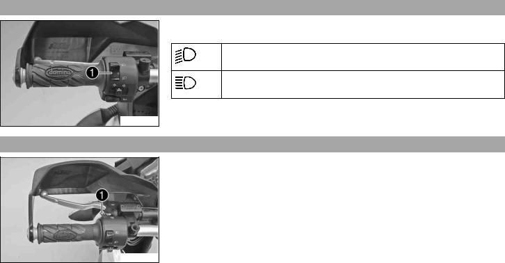
6.5 Light switch
The light switch 1 is fitted on the left side of the handlebar.
Possible states
Low beam on – The light switch is turned downward. In this position, the low beam and tail light are switched on.
High beam on – The light switch is turned upwards. In this position, the high beam and tail light are switched on.
B00684-10
6.6 Headlight flasher switch
The headlight flasher switch 1 is fitted on the left side of the handlebar.
Possible states
• Headlight flasher switch in basic position
• Headlight flasher switch pressed – The headlight flasher switch (high beam) is operated in this position.
B00685-10
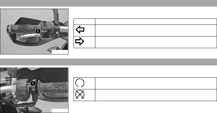
6.7 Turn signal switch
B00656-11
The turn signal switch 1 is fitted on the left side of the handlebar.
Possible states
Turn signal off
Left turn signal on – The turn signal switch is pressed to the left. The turn signal switch automatically returns to the central position after use.
Right turn signal on – The turn signal switch is pressed to the right. The turn signal switch automatically returns to the central position after use.
To switch off the turn signal, press the turn signal switch towards the switch case.
6.8 Emergency OFF switch
The emergency OFF switch 1 is fitted on the right side of the handlebar.
Possible states
Emergency OFF switch on – This position is necessary for operation as it closes the ignition circuit.
Emergency OFF switch off – In this position, the ignition circuit is interrupted, a running engine stops, and the engine cannot be started.
B00657-10
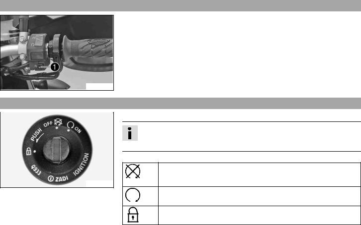
6.9 Electric starter button
The electric starter button 1 is fitted on the right side of the handlebar.
Possible states
• Electric starter button  in basic position
• Electric starter button  pressed – The electric starter is actuated in this position.
B00657-11
6.10 Ignition/steering lock
600825-01
The ignition/steering lock is in front of the upper triple clamp.
Info
The ignition may only be switched on using a black ignition key.
Use the orange programming key to activate and deactivate the black ignition key.
Possible states
Ignition OFF – In this position, the ignition circuit is interrupted, a running engine stops, and a non-running engine will not start. The ignition key can be removed.
Ignition ON – In this position, the ignition circuit is closed and the engine can be started.
Steering locked – In this position, the ignition circuit is interrupted and the steering locked. The ignition key can be removed.
| 6 | CONTROLS | 28 | ||||||
| 6.11 | Immobilizer | |||||||
| The electronic immobilizer secures the vehicle against unauthorized use. | ||||||||
| The immobilizer is activated automatically and the engine electronics are locked when the | ||||||||
| ignition key is withdrawn. | ||||||||
| The red warning lamp | flashes at 15 second intervals after one minute. | |||||||
| The red warning lamp can also indicate errors by flashing. | ||||||||
| Info | ||||||||
| The ignition key contains electronic components. Never attach multiple ignition keys | ||||||||
| to a single key ring; this may cause mutual interference and lead to problems. | ||||||||
| 400887-01 | A lost black ignition key must be deactivated to prevent unauthorized persons from operat- | |||||||
| ing the vehicle. | ||||||||
| The second black ignition key is activated when the vehicle is shipped. | ||||||||
| Another two spare ignition keys (key number on the KEYCODECARD) can be ordered from an | ||||||||
| authorized KTM workshop, but they need to be activated for use. | ||||||||
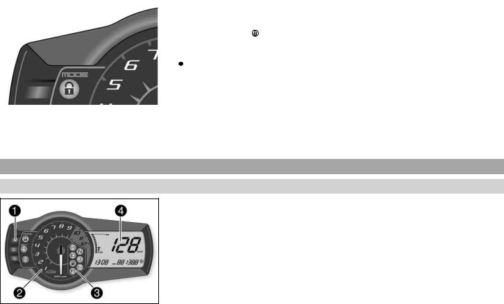
6.12 Combination instrument
6.12.1 Overview
The combination instrument is installed in front of the handlebar. The combination instrument is divided into 4 function areas.
1 Function buttons
2 Tachometer
3 Indicator lights
4 Display
400885-10
![]()
| 6 | CONTROLS | 29 |
| 6.12.2 | Function buttons | |
| You can change the display mode with the MODE button 1. | ||
| Possible display modes are the distance traveled (ODO), trip master 1 (TRIP 1), trip mas- | ||
| ter 2 (TRIP 2), and the ambient temperature. | ||
| Press the SET button 2 to reset the trip master 1 function (TRIP 1) and trip master 2 func- | ||
| tion (TRIP 2) to 0.0. | ||
| The ABS can be switched off using button 3. |
400886-10
6.12.3 Tachometer
The tachometer 1 shows the engine speed in revolutions per minute.
The red marking 2 shows the excess speed range of the engine.
400888-10
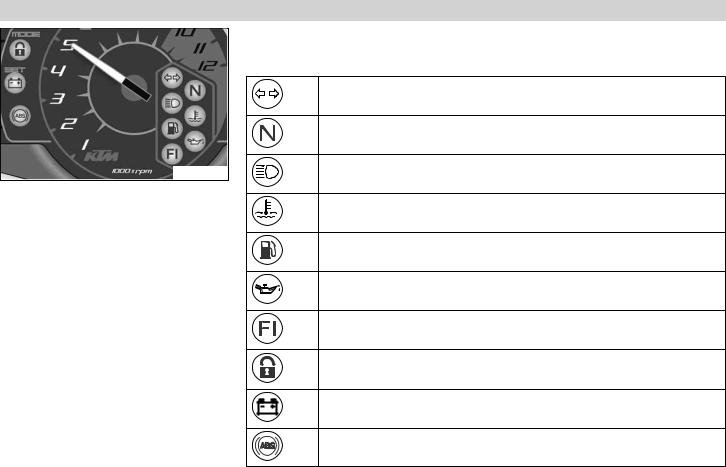
6.12.4 indicator lamps
400889-01
The indicator lamps offer additional information about the operating state of the motorcycle.
Possible states
The turn signal indicator light flashes green simultaneously with the turn signal – The turn signal is switched on.
The idling speed indicator lamp lights up green – The transmission is shifted to idle.
The high beam indicator light lights up blue – The high beam is switched on.
The temperature warning lamp lights up red – The coolant temperature has reached a critical value.
The low fuel warning lamp lights up yellow – The fuel level has reached the reserve mark. The display switches to TRIP F.
The oil pressure warning lamp lights up red – The oil pressure is too low.
FI warning lamp (MIL) lights up/flashes yellow – The OBD (on-board diagnosis) has detected an emissionor safety-critical error.
The immobilizer indicator lamp lights up or flashes red – Status or error message for immobilizer/alarm system.
The battery warning lamp lights up red – The voltage in the vehicle system is too low.
ABS warning lamp lights up/flashes yellow – Status or error messages relating to ABS (antilock brake system).
| 6 | CONTROLS | 31 |
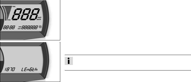
| 6.12.5 | Display | |
| When you switch on the ignition, all display segments light up for one second as a function | ||
| check. |
400892-01
LEnGth
Following the display function check, the LEnGth wheel circumference is shown for one second.
Info
1870 mm corresponds to the circumference of the 17" front wheel with a series production tire.
The display then changes to the last selected mode.
400881-01
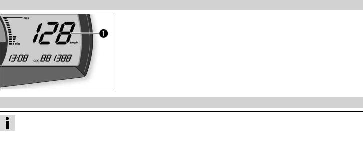
6.12.6 Speed display
The speed 1 is shown in kilometers per hour km/h or in miles per hour mph.
400838-10
6.12.7 Setting kilometers or miles
Info
If you change the unit, the value ODO is retained and converted accordingly.
Making the setting according to the country.
Condition
The motorcycle is stationary.
6 CONTROLS
33
– Switch on the ignition by turning the ignition key to the ON  position.
– Press the MODE button repeatedly until the ODO mode is active.
– Keep the MODE button pressed until the display mode changes from km/h to mph or from mph to km/h.
400893-10
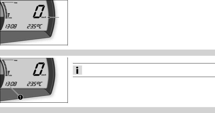
6.12.8 Time
The time is shown in area 1 of the display.
Info
After reconnecting the battery or changing the fuse, the time must be reset.
400893-11
6.12.9 Setting the clock
Condition
The motorcycle is stationary.
| 6 | CONTROLS | 34 | ||||||
| – Switch on the ignition by turning the ignition key to the ON | position. | |||||||
| – Press the MODE button repeatedly until the ODO mode is active. | ||||||||
| – Keep the MODE button and the SET button pressed simultaneously. | ||||||||
| The time display begins to flash. | ||||||||
| – Press the MODE button to set the hour. | ||||||||
| – Press the SET button to set the minute. | ||||||||
| – Keep the MODE button and the SET button pressed simultaneously. | ||||||||
| The time is set. | ||||||||
| 400893-12 | ||||||||
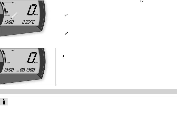
| 6.12.10 | ODO display | |||||||
| In the ODO display mode, the total distance traveled is shown in kilometers or miles. | ||||||||
| Info | ||||||||
| This value is retained, even if the battery is disconnected and/or the fuse blows. | ||||||||
400839-01
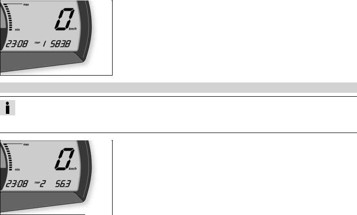
6.12.11 Setting/resetting display TRIP 1
Info
The TRIP 1 trip counter is always running and counts up to 999.9.
The trip counter can be used to measure the distance covered during trips or between two refueling stops. After the value 999.9 is reached, the trip counter starts at 0.0 again.
6 CONTROLS
35
– Switch on the ignition by turning the ignition key to the ON  position.
– Press the MODE button repeatedly until the TRIP 1 mode is active.
– Keep the SET button pressed.
 The TRIP 1 display is set to 0.0.
400840-01
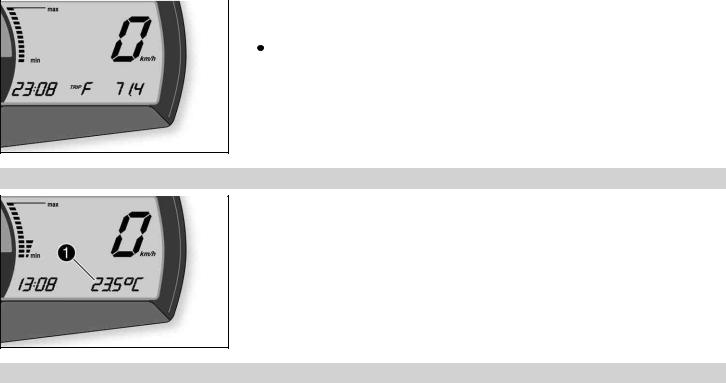
6.12.12 Setting/resetting display TRIP 2
Info
The TRIP 2 trip counter is always running and counts up to 999.9.
The trip counter can be used to measure the distance covered during trips or between two refueling stops. After the value 999.9 is reached, the trip counter starts at 0.0 again.
– Switch on the ignition by turning the ignition key to the ON  position.
– Press the MODE button repeatedly until the TRIP 2 mode is active.
– Keep the SET button pressed.
 The TRIP 2 display is set to 0.0.
400841-01
| 6 | CONTROLS | 36 | ||||
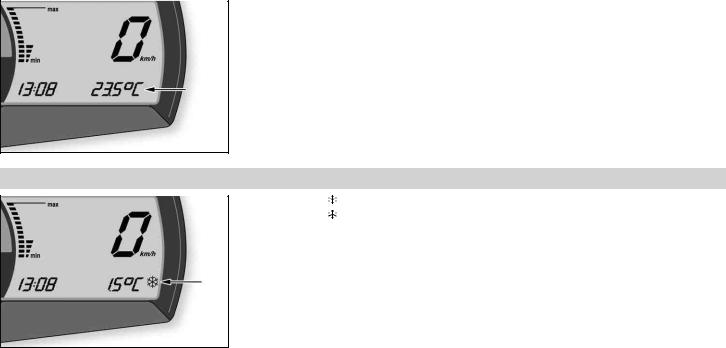
| 6.12.13 | TRIP F display | |||||
| If the fuel level drops to the reserve mark, the display automatically changes to TRIP F and | ||||||
| starts to count from 0.0, regardless of the previous display mode. | ||||||
| Info | ||||||
| The low fuel warning lamp lights up in parallel to the TRIP F display. | ||||||
400842-01
6.12.14 Ambient temperature indicator
The ambient temperature 1 is displayed in °C or °F.
400893-13
6.12.15 Setting the temperature units
Condition
The motorcycle is stationary.
6 CONTROLS
37
– Switch on the ignition by turning the ignition key to the ON  position.
– Press the MODE button repeatedly until the ambient temperature is active.
– Keep the MODE button pressed until the display mode changes from °C to °F or from °F to °C.
400893-14
6.12.16 Warning of icy roads
| The ice symbol | lights up to indicate an increased danger of slippery roads. | |
| The ice symbol | appears in the display when the ambient temperature drops below the | |
| specified value. | ||
| Temperature | 3 °C (37 °F) | |
The ice symbol  goes out in the display when the ambient temperature rises above the specified value again.
400894-10
| 6 | CONTROLS | 38 |
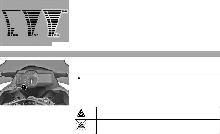
| 6.12.17 | Coolant temperature indicator | |
| The temperature display consists of 12 bars. The more bars that light up, the hotter the | ||
| coolant. When the upper bar lights up, all bars in the display begin to flash and the temper- | ||
| ature warning lamp lights up. |
Possible states
• Engine cold – Up to five bars light up.
• The engine is warm – Six to eleven bars light up.
• Engine hot – All twelve bars flash.
700124-01
6.13 Hazard warning flasher switch/hazard warning flasher
The hazard warning flasher switch 1 is fitted next to the combination instrument on the left.
The hazard warning flasher is used to indicate emergency situations.
| Info | ||||||
| The hazard warning flasher can be activated or deactivated while the ignition is | ||||||
| switched on or up to 30 seconds after the ignition is switched off. | ||||||
| Do not keep the hazard warning flashers activated longer than necessary as they | ||||||
| deplete the batteries. | ||||||
| B00658-10 | Possible states | |||||
| Hazard warning flasher off | ||||||
Hazard warning flasher on – All four turn signals, the hazard warning flasher switch, and the green turn signal indicator light in the combination instrument flash.
![]()
| 6 | CONTROLS | 39 |
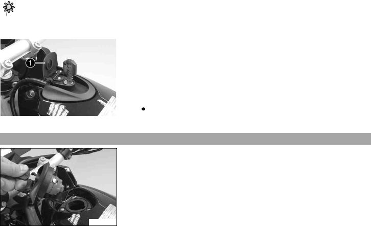
| 6.14 | Socket for electrical accessories | |
| Socket 1 for electrical accessories is fitted next to the ignition/steering wheel lock on the | ||
| left. | ||
| It is connected to the battery without an additional switch. | ||
Socket for electrical accessories
| Voltage | 12 V |
| Maximum current con- | 10 A |
| sumption | |
B00614-10
6.15 Opening the filler cap
Danger
Fire hazard Fuel is highly flammable.
– Never refuel the vehicle near open flames or burning cigarettes, and always switch off the engine first. Be careful that no fuel is spilt, especially on hot vehicle components. Clean up spilt fuel immediately.
– Fuel in the fuel tank expands when warm and can escape if the tank is overfilled. See the notes on refueling.
Warning
Danger of poisoning Fuel is poisonous and a health hazard.
– Avoid contact between fuel and skin, eyes and clothing. Do not inhale fuel vapors. If fuel gets into your eyes, rinse immediately with water and contact a doctor. Wash affected skin areas immediately with soap and water. If fuel is swallowed, contact a doctor immediately. Change clothing that has come into contact with fuel. Store fuel in a suitable canister according to regulations and keep it out of the reach of children.
| 6 | CONTROLS | 40 | ||||||
| Warning | ||||||||
| Environmental hazard Improper handling of fuel is a danger to the environment. | ||||||||
| – Do not allow fuel to get into the ground water, the ground, or the sewage system. | ||||||||
| – Lift the cover of the filler cap 1 and insert the ignition key. | ||||||||
| Note | ||||||||
| Danger of damage Ignition key breakage. | ||||||||
| – To take pressure off of the ignition key, push down on the filler cap. Damaged igni- | ||||||||
| tion keys must be replaced. | ||||||||
| – Turn the ignition key 90° counterclockwise and remove the filler cap. | ||||||||
| Info | ||||||||
| L00607-10 | ||||||||
| The filler cap has a tank air vent system. | ||||||||
6.16 Closing the filler cap
– Put the filler cap back on and turn the ignition key 90° clockwise.
– Remove the ignition key and fold down the cover.
L00608-01
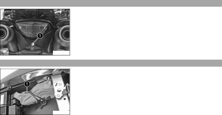
6.17 Seat lock
Seat lock 1 is located at the rear under the tail light.
It can be locked with the ignition key.
600922-10
6.18 Tool set
The tool set 1 is located in the storage compartment under the seat.
B00612-10
6.19 Handrails
The handrails 1 are used for moving the motorcycle around.
If you carry a passenger, the passenger can hold onto the handrails during the trip.
600923-10
6.20 Helmet lock
Warning
Danger of accidents Impairment of ride behavior and vehicle operation if a helmet or helmet lock is attached to the vehicle.
– Do not use the helmet lock for holding a helmet or other objects during the journey. Always remove the helmet lock before starting out.
The steel cable 1 in the tool set can be used to lock a helmet to the vehicle to prevent it from being stolen.
L00609-10
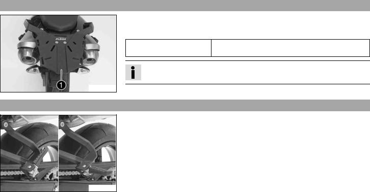
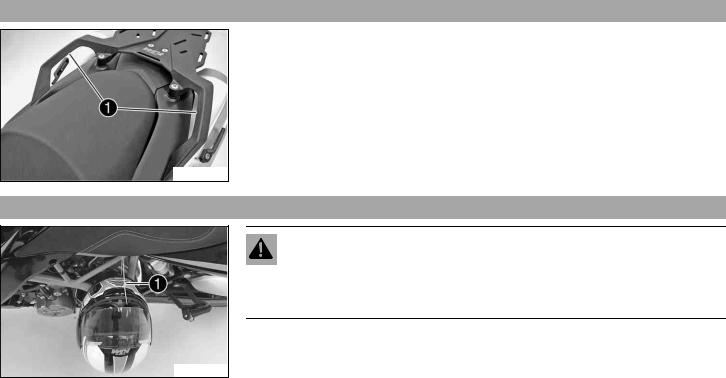
6.21 Luggage rack plate
The luggage rack plate 1 is located behind the seat.
The base plate of a luggage system can be mounted on the luggage rack plate (optional).
The luggage rack plate may not be loaded with more than the specified weight.
Maximum permissible load of 8 kg (18 lb.) luggage rack plate
Info
Follow the instructions provided by the luggage manufacturer.
L00605-10
6.22 Passenger footrests
The passenger footrests can be folded up and down.
Possible states
• Passenger footrests folded up – For operation without a passenger.
• Passenger footrests folded down – For operation with a passenger.
L00611-01
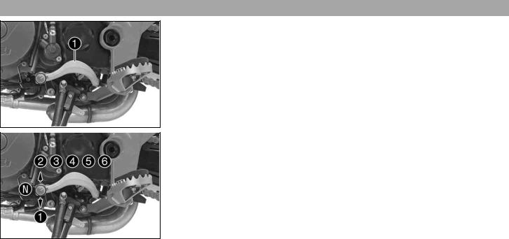
6.23 Shift lever
Shift lever 1 is mounted on the left side of the engine.
L00610-11
The gear positions can be seen in the photograph.
The neutral or idle position N is between the first and second gear.
L00610-10
| 6 | CONTROLS | 45 |
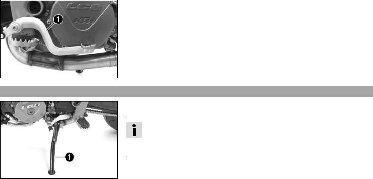
| 6.24 | Foot brake lever | |
| Foot brake lever 1 is located in front of the right footrest. | ||
| The rear brake is activated using the foot brake lever. |
L00613-10
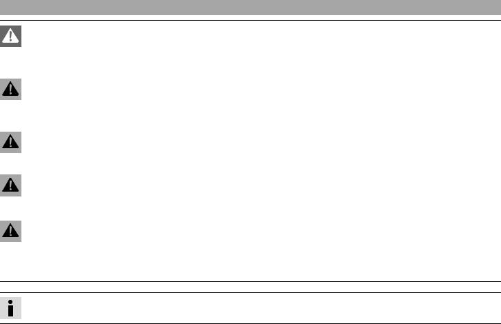
The side stand 1 is located on the left side of the vehicle.
The side stand is used to park the motorcycle.
Info
The side stand must be folded up during motorcycle use.
The side stand is coupled with the safety starting system – see the riding instructions.
Possible states
• Side stand folded out – The vehicle can be supported on the side stand. The safety starting system is active.
• Side stand folded in – This position is mandatory when riding the motorcycle. The safety starting system is inactive.
7.1 Information on first use
Danger
Danger of accidents Danger arising from the rider's judgement being impaired.
– Do not operate the vehicle while under the influence of alcohol, drugs and certain medications or physically or mentally impaired.
Warning
Risk of injury Missing or poor protective clothing presents an increased safety risk.
– Wear protective clothing (helmet, boots, gloves, pants and jacket with protectors) every time you ride the vehicle. Always wear protective clothing that is in good condition and meets the legal requirements.
Warning
Danger of crashing Poor vehicle handling due to different tire tread patterns on front and rear wheels.
– The front and rear wheels must be fitted with tires with similar tread patterns to prevent loss of control over the vehicle.
Warning
Danger of accidents Uncontrollable handling characteristic due to non-approved and/or non-recommended tires/wheels.
– Only tires/wheels approved by KTM and with the corresponding speed index should be used.
Warning
Danger of accidents Reduced road grip with new tires.
– New tires have a smooth rolling surface and therefore cannot provide full road grip. The entire rolling surface must be roughened in the first 200 kilometers (124.3 miles) by moderate riding at alternating angles. The full grip levels are not achieved until the tires have been run in.
Info
When using your vehicle, remember that others may feel disturbed by excessive noise.
– Make sure that the pre-delivery inspection work has been carried out by an authorized KTM workshop.  You receive a delivery certificate and the service record at vehicle handover.
– Before your first trip, read the entire operating instructions carefully.
– Familiarize yourself with the controls.
– Adjust the basic position of the clutch lever. ( p. 92)
– Adjust the basic position of hand brake lever. ( p. 95)
– Adjust the basic position of foot brake lever. ( p. 100)
– Get used to handling the vehicle on empty suitable terrain before making a longer trip. Try also to ride as slowly as possible to get a better feeling for the motorcycle.
– Hold the handlebar firmly with both hands and keep your feet on the footrests when riding.
– Run the engine in. ( p. 47)
7.2 Running in the engine
– Do not exceed the specified engine speed and load during the running-in period. Guideline
Maximum engine speed
| During the first: 1,000 km (621.4 mi) | 6,500 rpm | |
| After the first: 1,000 km (621.4 mi) | 9,600 rpm | |
| – Avoid full-throttle operation! | ||
7.3 Loading the vehicle
Warning
Danger of accidents Unstable handling characteristics.
– Do not exceed the maximum permitted weight and axle loads. The overall weight consists of: motorcycle operational and with a full tank, driver and passenger with protective clothing and helmet, baggage.

Warning
Danger of accidents Unstable handling characteristics due to incorrect mounting of suitcase and/or tank rucksack.
– Mount and secure suitcase and tank rucksack according to the manufacturer's instructions.
Warning
Danger of accidents Unstable handling characteristics at high speed.
– Adapt your speed according to your payload. If the motorcycle is loaded with luggage, ride more slowly.
| Maximum speed with luggage | 130 km/h (80.8 mph) |
Warning
Danger of accidents Destruction of luggage carrier system.
– If the motorcycle is fitted with luggage cases, note the manufacturer's specifications concerning the maximum payload.
Warning
Danger of accidents Poor visibility for other road users due to slipped baggage.
– If the tail light is covered, you are less visible to traffic behind you, especially in the dark. Check that your baggage is fixed properly at regular intervals.
Warning
Danger of accidents Changed handling characteristics and longer stopping distance with excessive payload.
– Adapt your speed according to your payload.
Warning
Danger of accidents Unstable handling characteristics due to slipped baggage.
– Check the way your baggage is fixed regularly.
Warning
Danger of burns A hot exhaust system can burn baggage.
– Fasten your baggage in such a way that it cannot be burned or singed by the hot exhaust system.
Source: https://manualmachine.com/ktm/990smt/7072983-user-manual/


0 Komentar